- 00989124780268
- info@araco.ir

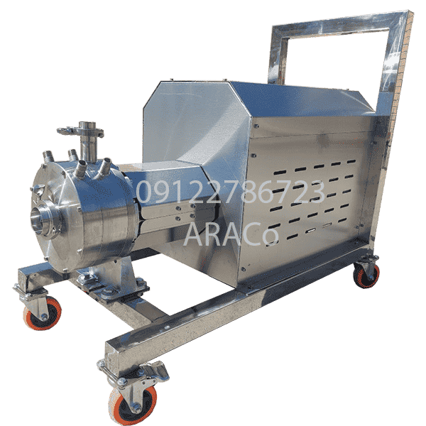
Application of homogenous mixer in the food industry Due to the high quality of fruits, vegetables, milk, and dairy products in Iran and the use of modern equipment, the food industry has grown significantly. Many Iranian food and dairy products are exported to neighboring and some European countries Products such as mayonnaise and ketchup, tomato paste, fruit concentrate, chocolate, milk, yogurt, butter, and other dairy products are possible. In many products, homogeneity is one of the important factors in quality and price. For this reason, if a company wants to make a good profit from its products, it must consider a high-quality level in production. Types of homogenizers in the food industry The model of the homogenizer in the food industry is selected based on the products, production volume, and the required amount of particle homogenization. The main examples that are used to produce the product are: - Bead mill homogenizer - High-pressure homogenizer (piston) - Stator homogenizer rotor homogenizer HS series steel homogenizer mixer is the highest class of ARACo homogenizer, which is a very good option for food, dairy, and pharmaceutical factories. We produce the HS series homogenizer from steel parts (SS316 or SS304) and we use the best quality brands in the market in the selection of bearings, couplings, and various components of this series. Contact us +989122786723(Whats App, IMO, Telegram) +982166561974 +982166129745
Continue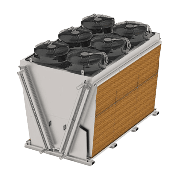
Combined air-cooled and water-cooled cooling(hybrid) As we explained in the previous articles, the hybrid cooling tower system is one of the ways to reduce water consumption. The main feature of the hybrid device is the use of air-cooled and water-cooled methods according to weather conditions. Adiabatic cooling is known as another way to save water. Of course, in many cases, the adiabatic cooling device is introduced as an adiabatic cooling tower. Typically, the price of an adiabatic cooling is in the range of a closed circuit hybrid cooling tower. Working method of adiabatic hybrid cooling tower Adiabatic cooling device consists of air cooled coil, evaporative pads, water spraying system, intelligent control system, fan and rotating equipment and body and chassis. In conditions where the air temperature is sufficient to reduce the fluid temperature to the desired value, this device works similar to a V-shaped cooler (cold months of the year). As the air heats up, the intelligent control system commands the adiabatic cooling to start spraying water on the pad. Water splashing on the pad and its evaporation leads to a decrease in the temperature of the incoming air. Therefore, in the hot months of the year and the summer season, Adiabatic cooling will be based on evaporation. Water consumption reduction calculations in adiabatic evaporative system To calculate the amount of water saving in the adiabatic system, we must check the annual meteorological information of the project along with the desired inlet and outlet water temperature of the project. By using the tables and curves of wet bulb temperature and dry air temperature, you can get the average annual savings of hybrid adiabatic cooling with an accuracy of 8-15%, which of course is part of the consulting services and in addition to the cost, requires The time is between 3 and 4 weeks. Contact us for consulting on hybrid cooling tower and adiabatic system in middle-east +989124780268 +982166561974 +982166129745
Continue
How does an air filter work? Dust and suspended particles are among the things that can damage equipment, machines, and devices. Air filters are usually used in industrial equipment to remove dust from the air. The filter is a plate which has network of fibers and prevents the entry of suspended particles larger than a certain size. Of course, filters are usually composed of several layers with different properties and each layer has unique properties. The airflow filter uses filters are common in industrial equipment. Some of the important uses of air filters are: - Car air filters - Filters used in air conditioners - Filters used in clean rooms - Filters for air conditioning - Filters used in masks and ... Filter CFD simulation The best method to understand the effect of the filter on the pressure drop and the way the airflow moves before building the device is the airflow simulation method(CFD). With the help of CFD Simulation, you can get the amount of pressure drop, airflow speed, and flow path inside the 3D geometry. Air filter simulation usually has graphs that define the pressure drop versus the airflow speed. This diagram provided by the filter supplier which shall be defined in the CFD simulation software so that the obtained results have good accuracy. To get more information and order an air filtering simulation, contact us. 09124780268 02166561974 02166129745 Related Links Airflow and fluid simulation services
Continue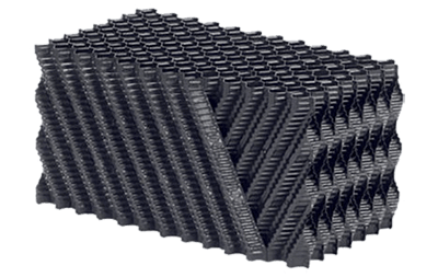
Cooling tower fillings classification The cooling tower is one of the most essential equipment in the factory production line. Among the cooling tower components, fillings can drastically change the efficiency and useful life of the cooling tower. Choosing "cooling tower fillings" wisely, we must understand their role. Cooling tower fillings have two essential functions: 1- Increasing the surface of evaporation in the cooling tower 2- Increasing the contact time between air and water in cooling water Both goals are about increasing the amount of water evaporation. Cooling tower fillings could be separated into two types of film and splash in terms of how they work in water evaporation. Cooling tower fills flute definition In film-type filling, shaped sheets are connected together to form a fillings block. The distance between two sheets in a filling block is called the FILLS FLUTE SIZE. In other words, as you can see in the image below, if you measure the maximum distance of the hexagons in the honeycomb from the top of the block, the measured distance is twice the value of the flute. Cooling tower CTI standard, article and book free download ARACo cooling tower services and components
ContinueIn the SolidWorks part environment, what are the largest drawable model dimensions? Solidworks software, like many design software, has predefined limitations. These restrictions are applied by the software manufacturer by default in different versions. In this article, we want to provide explanations about dimensional frameworks in SolidWorks. The size limit in the SolidWorks sketch One of the most important frameworks, is applied to the upper limit of sketch and feature dimensions in the Solidworks part environment. It might be interesting to know that, in a Part SolidWorks environment, you cannot sketch with one of its dimensions exceeds 1000 meters. If the length or width of one of the drawn lines or curves (side or diameter) exceeds a thousand meters, the software will warn you by giving a message that it is not possible to draw the desired sketch. In this case, an explanation is necessary. For example, if you draw a large square, the length of each side should not exceed 707 meters, because otherwise, the diameter of the square will reach over 1000 meters. Maximum dimensions in the solidworks features In addition to the sketch tab, the features section also has dimensions constraints. When you want to add volume to the 2D air drawing using feature commands (such as Extruded boss/base), you will have with a limit of 500 meters from each side. Of course, this 500 meter size frame in the section of SolidWorks profiles will apply to one direction. So you can add volume to the sketch by 500 meters in two opposite directions(1000 meters in total), as you can see in the following images. Is it possible to draw a model whose largest size is more than 1000 meters with Solidwork? Due to the dimensions limits, You can not create the part larger than 1000 meters(In any dimensions). But you can convert the desired model into smaller pieces. In such a way that the largest size is not more than a thousand meters. Next, you can enter these parts into the assembly part so that you can ignore part of the frames related to the dimensions. Related Links Free download Solidworks PDF Solidworks 3D model Solidworks services
Continue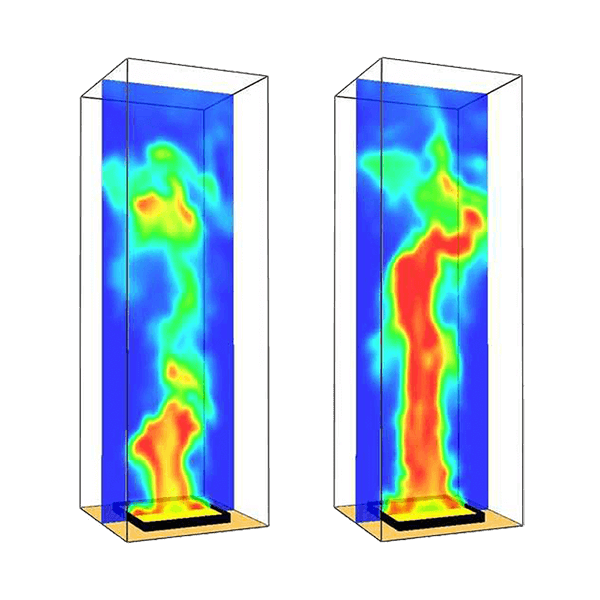
Simulation of flame behavior(torch and industrial burner) Chemically, the flame is the base division of the fire, which has a lot of heat and chemical reactions take place in it. The flame conditions, its size, and the geometric form that comes out of an industrial burner are critical. For example, in an industrial gas heater unit, the usually large flame must be created. If we consider the air inlets, we realize that this flame must burn in a way that does not collide with the boundary. That is where simulation and modeling help us predict flame behavior. For another example, consider that you want to implement a design for the geometric form and walls of a furnace or boiler combustion chamber. In this case, the design could be optimized, by modeling the flame geometry. Applications of flame simulation - Checking the geometry of the design and making sure that the flame does not collide directly with the body of the chamber - Assessing the condition of fresh air intakes - Estimation of the temperature situation in different places - Simulation of the combustion chamber of an industrial boiler - Simulating and optimizing the furnace flame simulationFlame modeling Effect of time in predicting flame behavior Considering the time factor, there are two types of simulation in fluid mechanics. The first mode, which is known as steady-state simulation, is executed in conditions where we want to see how the system works in normal mode. For example, CFD simulations of ventilation are usually steady state. This type of simulation can be done based on the system reaching the equilibrium state. Another type of simulation is called time-transient simulation. In the transient state analysis, it is assumed that the volume of the criterion has not reached equilibrium, and for this reason, the output information will change according to time. Modeling the behavior of fire and smoke is an example of the transient state. The simulation of the flame behavior can be performed in both stable and transient states. The choice between these two methods depends on the employer's expectations. For example, if we want to check the flame shape in an industrial burner, steady-state simulation is acceptable. But if we want to know about the geometrical form and temperature conditions of a large boiler (from the start of the operation), time-transient simulation is the correct choice. In the image below, you can see the results of flame shape analysis in a transient simulation. Flame shape modeling We are ready to simulate industrial burners and flames based on the client's needs in ARACo. Contact us for more information. +989124780268 +982166561974 +9821661297745 ARACo Simulation Services
Continue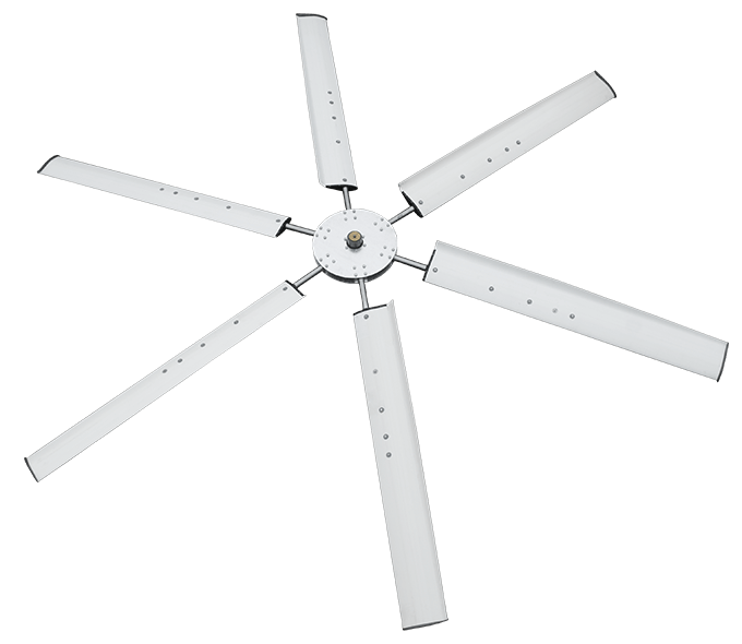
Cooling fan The fan in the cooling tower is responsible for creating airflow to increase evaporation efficiency. The higher the quality of the fan and blades, the lower the power consumption and the less vibration the device will have. Of course, just as choosing a poor fan with less aeration than the design conditions can prevent the cooling water from reaching the desired cold temperature, too large blades at high speeds can cause the droplets to splash out too much. Will increase water consumption in the cooling tower. Classification of fan cooling tower based on location As you know, cooling towers are divided into two types of suction and blowing in terms of airflow. Metal cooling towers are usually of the blowing type, the fan of which is located at the air inlet and is usually made of the centrifuge type (centrifugal). That sucks the air out. The fiberglass cooling tower, which is better known in the industry, is also of the suction type (Induced draft cooling tower), which consumes less electricity than the forged draft cooling tower. Our description in this article is about cooling tower suction fans, which are of the axial fan type. Cooling tower fan material Since the diameter of the blades varies according to the dimensions of the cooling tower, the material of the blades also largely depends on the diameter. For diameters greater than 2 meters, your choice is to use a fiberglass fan. Of course, in some cases, aluminum and metal fans have been used in older cooling towers. Plastic fan (Multi-Wing fan) This model of blades, which are usually made of plastic injection, is for use in small towers and is used up to 1.5 to 2 meters in diameter. In diameters between 0.5 meters to 1.5 meters, some manufacturers also use metal impact fans, which are slightly heavier. Aluminum or metal fan Many old concrete cooling towers used aluminum, galvanized, or steel blades. The reason for using this type of blade was usually that the composite technology had not grown as it does today. Among these blade and fan models, the aluminum blade, which is produced using the Poltrud method and in the form of a blade, is still used in some projects. The aluminum fan used in projects in Iran is usually the product of companies such as ilmed fan or Cofimco fan, which will be very expensive and difficult to import due to the rising price of the dollar. The best option to replace the aluminum fan is to use a fiberglass composite blade with heat and corrosion-resistant resin. Fiberglass Airfoil Fan Advances in the field of composite materials in recent decades have opened the door to the ventilation industry. The characteristics of a composite fan (fiberglass is a type of composite) are lightness, high strength, resistance to direct sunlight, and the ability to create radiations in the radius. Because of these unique features, if you want to buy a fan with a diameter of 2 meters (approximately 6 feet) to 7.5 meters (25 feet) for a cooling tower or air cooler, the fiberglass fan is the best choice. It may be interesting to know that the fiberglass fan itself can be produced in both blade and twisted forms, each of which has its characteristics. With the help of modern fan design software, using modern design and simulation methods, and unique experience in the field of cooling towers and air conditioners, we can produce cooling towers and air conditioners up to 7.5 meters in diameter. All produced blades are delivered with galvanized or steel hubs and clamps in a completely balanced set. For inquiries about the price of fiberglass fans and blades with a diameter of more than 2 meters in Iraq, Oman, Kuwait, Qatar, Saudi arabia and UEA contact us: Contact us : +989124780268 (WhatsApp,IMO,Telegram) Email : info@araco.ir
Continue
Which version of Solidworks is better to install? If you also want to install SolidWorks software on your Laptop or PC system, you are probably wondering which version of SolidWorks is better to install? This question is related to the specifications of your computer. For example, if the hardware to install Solidworks is relatively old, it is better not to use the latest versions available in the market. What windows are required to install SolidWorks? In addition to the hardware, the type of Windows and version of your operating system can also influence the choice of SolidWorks version. Remember that to install SolidWorks 2021 or 2022, you must use the 64-bit version of the Windows 10 operating system. It is not possible to install SolidWorks 2021 on Windows 8, Windows 8.1, and Windows 7. Considering that the new versions of SolidWorks will no longer be installed on Windows 8 and Windows 7 or XP from 2021, I suggest that you upgrade your operating system to Windows 10 and X64, and then software. Install the software. Solidworks/windows compatibility Tabel Windows 11, X64 Windows 10, X64 Windows 8, X64 Windows 7, X64 Solidworks Version YES YES NO NO Solidworks 2022 sp2 and higher NO YES NO NO Solidworks 2022 sp1 NO YES NO NO Solidworks 2021 NO YES NO YES Solidworks 2020 NO YES NO YES Solidworks 2019 NO YES YES YES Solidworks 2018 NO YES YES YES Solidworks 2017 Installing and running SolidWorks on Windows 11 According to the SolidWorks website installation requirements section, only service pack2 of SolidWorks 2022 can be installed on Windows 11. For this reason, we suggest that before installing Windows 11, be sure to run software such as SolidWorks. So you should not install Solidworks 2021 or 2022 on windows 11. Which version of SolidWorks should we use? If you have powerful and up-to-date hardware (CPU, RAM, and graphics card) and you are learning SolidWorks, I think you should start with the latest service pack from last year's version. For example, now in 2022, my suggestion is that Solidworks 2021, Service pack 2, and SP3 are good options. This proposal has a reason. Because new service packs of each version usually fix bugs and problems, and when working with SolidWorks, the system hangs less or leaves the program. Of course, if you want to learn SolidWorks and because of work problems, you can not buy a professional system right now, Solidworks 2018 and 2016 are good options and could run on medium laptops. Related links Solidworks training and tutorial PDF Free download Free download Solidworks, Catia and Cad 3D model Solidworks design and modeling service Solidworks simulation service Contact Us +989124780268 (WhatsApp, Imo, Telegram)
Continue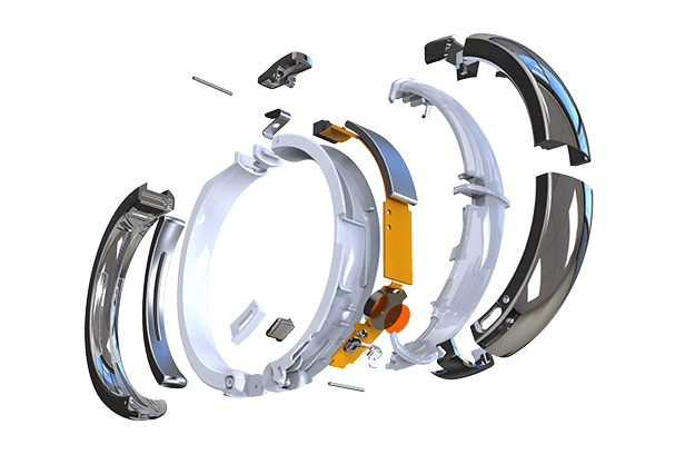
What does product design mean? "Every time you think you have paid a lot for a good design, you have to Think of the huge costs that a bad (cheap) design imposes on you," says Dr. Ralph Speth, CEO of Jaguar and Land Rover, who also has a track record at BMW. Product design means the process of reviewing, providing solutions, manufacturing, and product presentation to meet a need. In a word, product design means the characteristics of an artifact including its form and shape (from an aesthetic point of view, the tactile sense of a device) and its function (including capabilities). But as a process, it means a set of actions and strategies, from the Idea Generation stage to the final stage of Commercialization. In general, product designers conceptualize and evaluate different ideas and then define them as research in industrial and scientific formats. ARACo Solidworks design and 3D modeling services in middle east Product design steps from idea to production As a process, Product design means a set of actions and strategies, from the Idea Generation stage to the final stage of Commercialization. Basically, product designers conceptualize and evaluate different ideas and then define them as research in industrial and scientific formats. As a word, product design means the characteristics of an artifact, including its form and shape (from an aesthetic point of view, the tactile sense of a device) and its function (including capabilities).The importance of product design and industrial design in the success of the company The role of product designers is to combine art, science, and technology to create services and products that people or companies use. Meanwhile, one of the weaknesses in our country in the design and development of products is the lack of sufficient attention to technical features, manufacturing capabilities, and cost. Observing these points requires expertise, information, and engineering knowledge along with production experience. With these explanations, only the beauty of a product cannot guarantee its success in the market and get a good market share. Rather, the designed product must have high quality, good service life, low failure, and reasonable and relatively low cost to be successful in the market. The pictures below show an example of some industrial products designed by Araco that have also reached the production stage. Sample product design and industrial design projects of Araco Company A professional designer knows that product design is not just an artistic process, but a technical-artistic project that ultimately remains just an idea without the factors of buildability, maintenance, and final cost. For more information, please contact us Product design and industrial design Evaluate ideas and advice in the field of commercialization 3D modeling of an industrial project using SolidWorks Concept design and detail design services Please do not hesitate to contact us for more information: +982166129745 +989124780268 +989358322301 Solidworks blog : http://solidworks-iran.blog.ir/page/Solidworks-Services-Iran-Middle-east-Canada-Australia-Europe See our product design samples on Instagram: https://www.instagram.com/araco.ir
Continue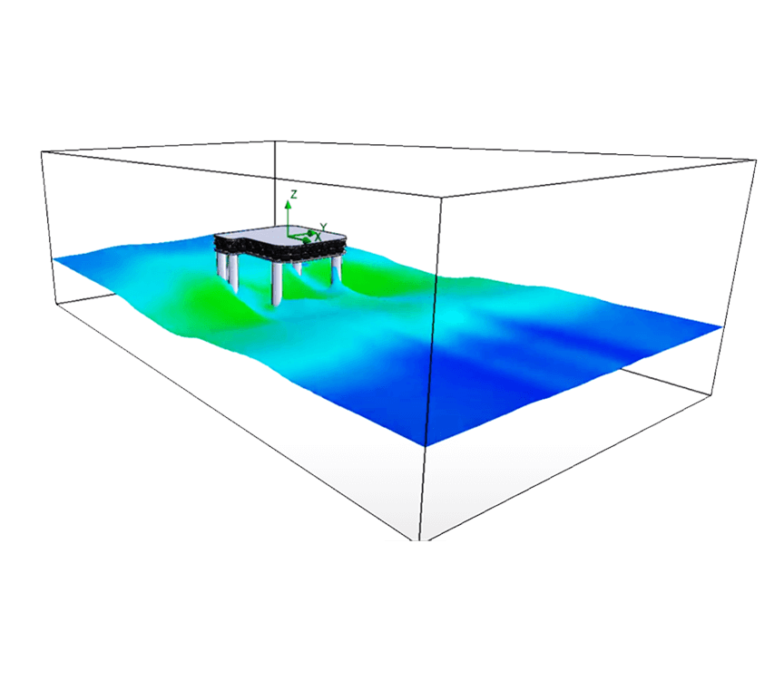
One of the methods used in engineering sciences to predict conditions in the environment is simulation. Simulation has different types and is very common in mechanical, electrical engineering and medical engineering, etc. Simulation predicts how the system will behave in a certain situation. With the help of analysis results and outputs, we can find out about the status of a system in the desired conditions and if we see a weakness or problem, we can fix the system or device with the lowest possible cost. Simulation benefits Analysis and simulation is one of the ways to reduce the costs of designing and making prototypes. For example, when a company produces a new product, before introducing the product to the market, with the help of related software, it performs various simulations on the a product and optimizes the product design. Otherwise, the product may have many problems and defects after entering the market and damage the reputation of a company. Free surface simulation One of the types of simulation is simulation and simulation of fluids and heat transfer. In fluid simulations, the behavior of liquid or gas in the environment is predicted. Among the things that are obtained in the analysis of fluids and heat transfer, we can mention pressure, temperature, speed and the way the fluid moves. Liquid free surface simulations are also a subset of CFD analysis and simulation. Analysis and modeling of the movement of liquid like water inside channels and chambers where the liquid surface is in contact with air is known as two-phase flow simulation or free surface. The complexity of this type of simulation is mostly due to the fact that the geometric form of the surface of water or other fluids changes due to movement, displacement and other factors. Simulation of water movement in the open channel, simulation and modeling of water flow inside the open channel of the river In this way, the simulation of the fluid movement is dependent on time, and this type of simulation is called Time transient simulation. In this simulation method, the simulation time is specified and unlike Steady State simulations, the simulation result is not related to stable conditions. For example, in simulating the way water drains from the back of a dam, it is possible to simulate the geometry of the water surface in a certain period of time. Another case of simulation of liquids and fluids in this case is the intensity and manner of the impact and momentum of the liquid on the walls of the tank in lateral shocks. An example of this type of simulation is the force from the liquid into the body of the tanker. Some examples of free surface liquid flow simulation are: - Simulation of water flow inside the channel - Simulation of how liquid moves inside the tank - Wave simulation and modeling - Simulation of the movement of frigates, boats and ships in the water - Modeling fluid movement inside the tank - Flood simulation Flood modeling An example of the simulation of the movement of water inside the canal by Araco Simulation and modeling of the movement and impact of water waves on the marine platform by Araco Wave simulation Araco company, with a lot of experience in industrial analysis and simulations, is ready to perform all kinds of free surface simulations in Solidworks - Simulation of water movement in an open channel - Simulation of liquid movement in the tank - Simulation and simulation of waves - Analysis and simulation of the effect of waves on marine structures - Simulation and modeling of floods and landslides Araco Company - Mohammad Ghorbanalibeik Direct contact number: +989124780268 Company contact number: +982166561974-+982166129745 ARACo simulation services Solidworks weblog
Continue
Industrial consulting and product optimization How can we optimize a product? What are the processes and methods of prototyping and endemic manufacturing of products or machines? How can we define the relationship between R&D, manufacturing, and QC teams? Is there any way to make prototyping more productive? Which one should we focus on? Time, cost, or quality? What can we do to reduce the manufacturing cost and where, to begin with? What are the differences between product design, reverse engineering, and a copy? These and many other questions need to be asked before a manager decides to enter a new market. Without a doubt, management has differences, as well as similarities in distinct branches and these differences, make demand for professional knowledge in any field of business for a manager. Defining the market and product, bench marketing, study the weaknesses and strengths, reverse engineering and re-design, patent-pending, prototyping and mass producing, marketing, system control and systematic innovating are all strategic necessities of a business that needs planning. One of the key points of this section is developing a new product, and to achieve this goal there are usually two procedures: reverse engineering or product design. Reverse engineering is the procedure of obtaining technical knowledge by studying its similar products. Unfortunately many mistake the phrase “Studying” with “measuring” and they only check dimensions, materials, surface hardness, and other physical properties. But reverse engineering means understanding the reason behind every choice in process of engineering design. This is the only way that a company achieves technical knowledge and will be able to develop a product by itself. Another reason behind this “studying” is to endemic a product. For example, the main product may use imperial units, but your country uses metric units. The size of standard parts like bolts, bearings, profiles, etc. are different and therefore you need some analysis before replacing them. ARA Co with its extensive experience in reverse engineering and design of new products is now ready to share its knowledge with industries and investors in the following sectors: Marketing and sale engineering Business development/start-up from prototyping to mass production Reverse engineering and product design consulting Industrial design, engineering design, and product design Power calculation and selection of power supply chains such as electric motor and gearbox Please do not hesitate to contact us for more information: +982166129745 +989124780268 +989358322301 See our project samples on Instagram: https://www.instagram.com/araco.ir Solidworks online projects and training courses Solidworks Tutorial & Training PDF Free Download
Continue
Reverse Engineering and Industrial Design Online Solidworks design project Reverse engineering and components manufacturing Reverse engineering, also called back engineering, is the process of extracting knowledge or design information from a product and reproducing that, based on the extracted information. The process often involves disassembling something(a mechanical device, electronic component, computer program, or biological, chemical, or organic matter) and analyzing its components and workings in detail. For the perfect implementation of design and reverse engineering, knowledge of engineering and at the same time manufacturing experience is very important. Now day’s engineering Knowledge is usually related to mechanical software, which includes the preparation of a 3D model of the component or point cloud, analysis, and final drawings. ARACo with highly qualified employees is ready to convert all components and samples to the 3D model using the cloud of points or advances 3D modeling technics with Solidworks. In the field of manufacturing components and machines, ARACo with different processes such as machining, metalworking, cutting, welding, and casting, can build small and medium-sized parts and metal equipment. Contact us : Info@araco.ir Cell phone : +989124780268 (Whats app - Telegram - Imo) Office : +982166561974 , +982166129745 ARACo Solidworks blog Solidowkrs design project sample, Instagram Solidworks online projects and training courses Solidworks Tutorial & Training PDF Free Download ARACo design and prototyping - Solidworks project samples
Continue
Powerful and professional PC needs for SolidWorks software Minimum hardware configuration required for SolidWorks 2021 and 2020 Good and suitable laptop specifications for SolidWorks Any software, in addition to a proper operating system, requires good hardware to run fast and smooth. By hardware we usually mean CPU processing power, amount of RAM and RAM speed, amount of free space on the hard drive and graphics card specifications. Of course, in engineering software, we can usually run the software with medium system specifications, but if we want to use all its power, we must use powerful systems known as workstations. The method of choosing a suitable desktop or laptop to run Solidworks software is a question for many users. In this article, we try to talk about the computer specifications suitable for using SolidWorks. Before continuing the article, we want to explain the difference between 32-bit and 64-bit Windows (operating system). What is the difference between Windows x64 and x86 or 32 bit and which is better for installing SolidWorks? A very important point when installing SolidWorks is, does SolidWorks support your current Windows? For example, SolidWorks 2021, 2020 and 2019 will not run on Windows 8.1. Or SolidWorks 2021, which is the latest version of the software, no longer supports Windows 7. To find out which versions of SolidWorks each operating system supports, we need to refer to the SolidWorks website and operating system section. Now the question we ask is which version of 32-bit or 64-bit Windows is suitable for solid. The main difference between 32-bit Windows, also known as x86 windows, and the 64-bit version is that 32-bit Windows supports a maximum of 4 GB of RAM due to the type of architecture and memory addressing. This means that if you buy a powerful laptop with 32 GB of RAM and install Windows 8.1 32-bit version on it, you can only use 4 GB of RAM! Besides, many 32-bit malware do not run on 64-bit Windows. That's why the best option is to use Windows X64 to run and install Solidworks. System specifications and hardware in the main SolidWorks environment Solidworks part Solidworks assembly Solidworks drawing In general, there is no specific limit on the minimum configuration to run SolidWorks. (Unless your computer has very poor configuration or specifications) In fact, you can run SolidWorks with an Intel Core i3 processor and 4 or 8 GB of RAM. At the same time, Solidworks offers the minimum system specifications as follows: Solidworks 2020 and 2021 minimum hardware requirement Processor (CPU): 3.3 GHz or higher clock speed Operating System: Windows 10 64-bit Memory: 32GB (16GB minimum) Hard Drive: Solid State Drive (SSD), maintaining at least 20GB free space Graphics Card: NVIDIA Quadro P600 (entry level), P1000 / 2000 (mid-range) or P4000 (high-end) AMD Radeon Pro WX 3100 (entry level), WX 4100 (mid-range) or WX 5100 (high-end) In 3D modeling, sketching, and assembly, SolidWorks typically uses the power equivalent to 1 CPU core. In this way, as the speed and frequency of the main CPU increase, SolidWorks performs better in its primary environments, including part, assembly, and drawing. The recommended CPU frequency for Solidworks, especially the 2021 and 2020 versions, is 3Ghz to 3.3 GHz. By processing speed of each core (Core) in the CPU, we mean the normal processing frequency (Clock speed). So with that said, for modeling, assembly, and drawing in SolidWorks, the benchmark and CPU score in single-core mode should be high. Therefore, although the number of cores and CPU threads in different environments such as simulation environment, fluid simulation and heat transfer, rendering and animation of SolidWorks software has a great impact, but in the initial environments of solid software, single-core processor speed That has an impact. One of the great websites where you can check the specifications of each processor and compare it with other CPUs or so-called benchmark, is https://www.cpubenchmark.net/cpu_list.php . High RAM and graphics card quality are more useful in assembly environment. These two characteristics are most effective in complex SolidWorks assemblies with a large number of components. Using a high-speed hard drive and SSDs as the main Windows drive that also has SolidWorks installed will increase the speed and load of Solidworks, but its absence will not be a problem. PC specifications for SolidWorks simulation When using Solidworks Simulation and especially meshing parts or assemblies in SolidWorks and performing the trial and error process when performing SolidWorks simulation, all the main processor cores are activated and more CPU cores are more useful in this environment. Also, when performing Meshing operations for a model in SolidWorks stress analysis and CFD environment, the high amount of RAM helps to do smaller meshing, which is necessary for situations where high simulation accuracy is required. The graphics card and its specifications have little effect on the speed of the SolidWorks simulation and simulation environment. Specifications of PC and Laptop system required for SolidWorks rendering environment Solidworks photo view - Rendering It is important to note that Solidworks software uses the main processor when rendering, and in SolidWorks, the graphics card does not interfere much in rendering. Suitable CPU for SolidWorks Therefore, the stronger the CPU and the more cores it has, the faster the rendering speed will be. It should be noted that the English code after the name of the processor represents its family. U-code CPUs, which are ultra-low consumption and are used in many laptops today, generally have 2 main cores and 2 virtual cores. Meanwhile, processors with Q, QM, and HQ codes have 4 main cores and 4 virtual cores (thread), and their use increases the speed of rendering, animation, as well as simulation, and simulation in SolidWorks. It is interesting to know that from the 8th generation onwards, Intel Core i7 processors, U code CPUs also have 4 main cores and 4 virtual cores. For example, if you use the Intel Core i7-8550U processor to run SolidWorks software, this processor, which belongs to the 8th generation of Intel products, has 4 cores and 8 threads, unlike the previous series of U code. We suggest that you visit the benchmark site www.cpubenchmark.net for a specialized review of the processor performance status, and after searching for the processor you want, read its specifications carefully. In addition to all this, the new Xeon series processors are also good options for rendering, making industrial animation with SolidWorks, and performing simulation and simulation in SolidWorks. Another good option for choosing a Solidworks CPU is to use the Intel Core i9 series. This series of Intel processors have a relatively good number of cores and threads, and at the same time, its price is usually cheaper than the Intel Zeon series. Useing AMD processor to run SolidWorks One of the questions about Suitable CPU for Solidworks is, does SolidWorks software run with AMD CPU. The answer to this question is yes. SolidWorks runs on PCs and laptops with AMD processors. AMD processors usually have more cores than Intel CPUs due to their lower price. For example, the AMD Thread ripper series is one of the options for SolidWorks desktop and workstation and performs well in Solidworks rendering, Solidworks Simulation and CFD fluid simulation. Suitable graphics card(GPU) needed to run SolidWorks As explained, ordinary graphics cards are also capable of running SolidWorks. Rendering and creating animation is the responsibility of the main processor or CPU. Note that if you use graphics cards approved by Solidworks, you can download their driver from the SolidWorks site and use some special features such as Real view. Of course, the price of these graphics cards is very high and it is not necessary to use them except in special cases. In many cases, users even use Onboard graphics cards. SolidWorks-approved graphics cards include: NVIDIA Quadro series AMD FirePro series Link to the approved graphics card review page based on system specifications https://www.solidworks.com/sw/support/videocardtesting.html The effect of RAM on the execution of Solidworks SolidWorks does not require much memory (RAM) when running. In SolidWorks software, we need memory and RAM when, for example, we want to open an assembly with a large number of parts or work in areas such as simulation and simulation. One of the cases where SolidWorks requires high RAM and memory is the meshing operation in static analysis and stress analysis of SolidWorks-Solidworks simulation meshing. In the field of fluid simulation and heat transfer of solidwork and especially mesh, a three-dimensional model requires high memory or RAM to start the simulation. ARACo Worldwide Solidworks design, simulation and animation service Free download Solidworks PDF, tutorial, Ebook and trainings Solidworks weblog
Continue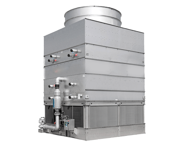
Cooling tower manufacturer in middle east We are ready to provide the best fiberglass cooling tower made in Iran with Germany parts. Our cooling towers are using widely in different applications such as Steel, Zinc, Diary, Paper, Chemical, Petrochemical, Power plants and ... Industries. We also manufacture a package cooling tower for HVAC uses. Our Fiber glass counter flow Cooling towers made from the best quality materials and we could guaranty the performance for Industrial uses. The following link is a great reference for download cooling tower documents, standards, and books. Cooling tower CTI standard, article and book free download Fiber glass cooling tower and component in Iraq Fiberglass industrial Cooling tower and Cooling tower fill - Turkey Cooling tower in Azerbaijan Fiberglass and industrial cooling tower Cooling tower PVC filling Cooling tower PP fill Cooling tower composite and fiber glass fan Cooling tower net splash fill Cooling tower spare parts Cooling tower design and simulation Cell phone: +989124780268 (IMO, Telegram, What's app) Office : +982166561974 & +982166129745 Cooling tower weblog
Continue
Solidworks project and industrial design in Germany The economy of Germany is a highly developed social market economy. It has the largest national economy in Europe, the fourth-largest by nominal GDP in the world, and fifth by GDP (PPP). In 2017, the country accounted for 28% of the euro area economy according to the IMF. Germany is a founding member of the European Union and the Euro zone. In 2016, Germany recorded the highest trade surplus in the world worth $310 billion, making it the biggest capital exporter globally. Germany is the third largest exporter in the world with 1.21 trillion euros ($1.27 trillion) in goods and services exported in 2016. The service sector contributes around 70% of the total GDP, industry 29.1%, and agriculture 0.9%. Exports account for 41% of national output.[needs update] The top 10 exports of Germany are vehicles, machinery, chemical goods, electronic products, electrical equipment, pharmaceuticals, transport equipment, basic metals, food products, and rubber and plastics. The economy of Germany is the largest manufacturing economy in Europe and it is less likely to be affected by the financial downturn and conduct applied research with practical industrial value and sees itself as a bridge between the latest university insights and industry-specific product and process improvements, and by generating a great deal of knowledge in its own laboratories as well. Industry and construction accounted for about 30% of gross domestic product, and employed also about 30% of the workforce. Germany excels in the production of automobiles, machinery, electrical equipment and chemicals. With the manufacture of about 5 million vehicles, Germany was the world’s fourth largest producer and largest exporter of automobiles. German automotive companies enjoy an extremely strong position in the so-called premium segment, with a combined world market share of about 90%. Small- to medium-sized manufacturing firms (Mittelstand companies) which specialize in technologically advanced niche products and are often family-owned and form major part of the German economy. It is estimated that about 1500 German companies occupy a top three position in their respective market segment worldwide. In about two thirds of all industry sectors German companies belong to the top three competitors. ARA Co engineering team with a great background in Solidwork software, is ready to handle world wide Solidworks project for many countries. We can work for some German companies in Solidworks design and Simulation (CFD,FEA) section. Our fields of activity in this section are : 3D Modeling Project by Solidworks Solidworks Sheet metal project Solidworks Structure and weldment project Reverse Engineering Industrial design Project Industrial and product Rendering CFD and FEM simulations and analysis Contact us : Info@araco.ir Official website : http://araco.ir/en Cell phone : +98 912 4780268 (Whats app - Telegram - Imo) Office : +98 21 66561974 , +98 21 66129745 Sample projects : www.instagram.com/araco.ir Solidworks source : http://solidworks-iran.blog.ir/page/Solidworks-Services-Iran-Middle-east-Canada-Australia-Europe Solidworks Tutorial & Training PDF Free Download Reverse Engineering and Industrial Design
Continue
Solidworks project in Canada Canada Economy The economy of Canada is a highly developed mixed economy with 10th largest GDP by nominal and 17th largest GDP by PPP in the world. Canada is one of the world's wealthiest nations with high standard of living and quality of life. As with other developed nations, the country's economy is dominated by the service industry, which employs about three quarters of Canadians. Canada has fourth highest total estimated value of natural resources, valued at US$33.2 trillion in 2016. It has the world's third largest proven petroleum reserves and fourth largest exporter of petroleum. It is also the fourth largest exporter of natural gas. Canada is considered an "energy superpower" due to its abundant natural resources. Canada is unusual among developed countries in the importance of the primary sector, with the logging and oil industries being two of Canada's most important. Canada also has a sizable manufacturing sector, based in Central Canada, with the automobile industry and aircraft industry being especially important. With a long coastline, Canada has the 8th largest commercial fishing and seafood industry in the world. Canada is one of the global leaders of the entertainment software industry. It is a member of the APEC, NAFTA, G7, G20, OECD and WTO. As a Solidworks service provider we recognize 4 Important Industrial sector inside Canada which could use our 3D Modeling, Simulation and design services. Canada Automotive Industry Cutting-edge R&D, unparalleled market access and seamless integration into the Great Lakes automotive supercluster make Canada the ideal choice to drive automotive innovation into the future. In 2013, Canada’s automotive manufacturing sector directly employed over 117,000 workers and generated revenues of $84.7 billion in 2013. Canada Aerospace Industry Canada’s aerospace sector is comprised of some 700 companies generating direct annual revenues of more than $28 billion in 2014. The industry is highly integrated into the global value chains and exports 80% of its production globally. Canada Machinery and Equipment Canada ranks among the world’s top machinery-manufacturing countries. For foreign investors in the machinery and equipment sector, domestic Canadian demand itself provides significant opportunities for growth. Medical Devices Canada offers a highly diversified, R&D intensive, technology based and export oriented medical device sector, with about 1,500 firms employing 35,000 people and exporting $1.9 billion worth of medical devices in 2013. ARA Co engineering team with a great background in Solidwork software, is ready to handle world wide Solidworks project for many countries. We are already working for some Canadian company in Solidworks and Simulation (CFD,FEA) section. Our fields of activity in this section are : 3D Modeling Project by Solidworks Solidworks Sheet metal project Solidworks Structure and weldment project Reverse Engineering Industrial design Project Industrial and product Rendering CFD and FEM simulations and analysis Contact us : Info@araco.ir Official website : http://araco.ir/en Cell phone : +989124780268 (Whats app - Telegram - Imo) Office : +982166561974 , +982166129745 Sample projects : www.instagram.com/araco.ir Solidworks source : http://solidworks-iran.blog.ir/page/Solidworks-Services-Iran-Middle-east-Canada-Australia-Europe Solidworks Tutorial & Training PDF Free Download Solidworks and Solidwork add in and plugin Free Download Reverse Engineering and Industrial Design
Continue
Mechanical Design or machine design is one of the branches of Engineering Design. To understand what exactly machine design or mechanical design is let us consider the example of the gear box of the car. The gear box transmits the motion and the power of the engine to the wheels of the vehicle. The gearbox comprises group of gears which are subjected to not only motion but also the load of the vehicle. For the gears to run at desired speeds and take desired loads it is important that they should be designed. During designing various calculations are performed considering desired speeds and loads and finally the gear of particular material and specific dimensions that can take all loads and that can be manufactured at least possible cost giving optimum performance is designed. In similar fashion all the components of the car, including engine, have to be designed so that they optimally meet all the functional requirements at lowest possible cost. This whole process of designing is called as machine design or mechanical design. Machine Design or Mechanical Design can be defined as the process by which resources or energy is converted into useful mechanical forms, or the mechanisms so as to obtain useful output from the machines in the desired form as per the needs of the human beings. Machine design can lead to the formation of the entirely new machine or it can lead to up-gradation or improvement of the existing machine. For instance if the existing gearbox is too heavy or cannot sustain the actual loads, entirely new gearbox can be designed. But if the same gearbox has the potential to lift more loads, it can be upgraded by making certain important changes in its design.
Continue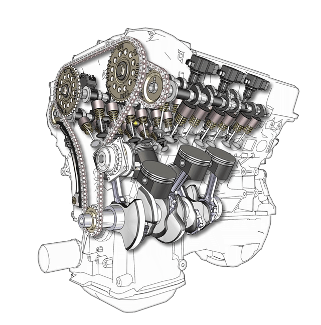
Revers Engineering - Part III In the past, explained the definition of reverse engineering, applications, and its objectives and basic information required for the reverse engineering process. It was also talked about the first part of this process, which is extracted dimensional information. In this article we will explain, in another process in reverse engineering is required. Each of the components of a system that is designed to achieve a specific purpose, requires certain features. In a car there are thousands of pieces that each of them has duty and should be designed to have the best performance. The tire must be flexible and at the same time show high resistance against tension and pressure. Be sure the chassis is rigid and as light as possible. The cylinder body should be cast easily and have a good turning capabilities and at the same time have a high heat transfer coefficient. Access to these features would not be possible without detailed information of ingredients piece and if that's not the same physical and chemical characteristics of the two pieces together, even with full compliance of dimensional characteristics, will remain incomplete reverse engineering process and the end product will meet the needs of the target. Author: Hossein Gorbanalibeik - Director of reverse engineering and modeling - Araco Company ARACo design service
Continue
Solidworks is better or Catia No doubt raised the question, for many factories, companies and students of mechanical engineering, who will choose which of the many applications of mechanical engineering. With the advent of software engineering and mechanical engineering at its head, has increased sharply, the pace of research and development products while at the same time reduced the cost of a product design to manufacturing process. Fifth-generation software for mechanical engineering, which are main arms companies at all stages of design, engineering and manufacturing, and are involved in all these processes, have created another leap in increasing the speed of technological progress. In fact, the process of design, engineering and manufacturing computer (CAD / CAE / CAM) has come to the help of engineers and designers, to pay higher accuracy to creativity and innovation. Of course, the process of design, engineering and manufacture of computer, fifth generation software for mechanical engineering. despite the late twentieth century, AutoCAD software, products of Autodesk company , the mechanical industry and its subset, construction industries and even electricity and telecommunications have been virtually unopposed, after the arrival of new software and increase the functionality of the software , companies, factories and universities moved towards them. http://solidworks-iran.blog.ir/post/Solidworks-or-Catia-Comparison-Middle-east
Continue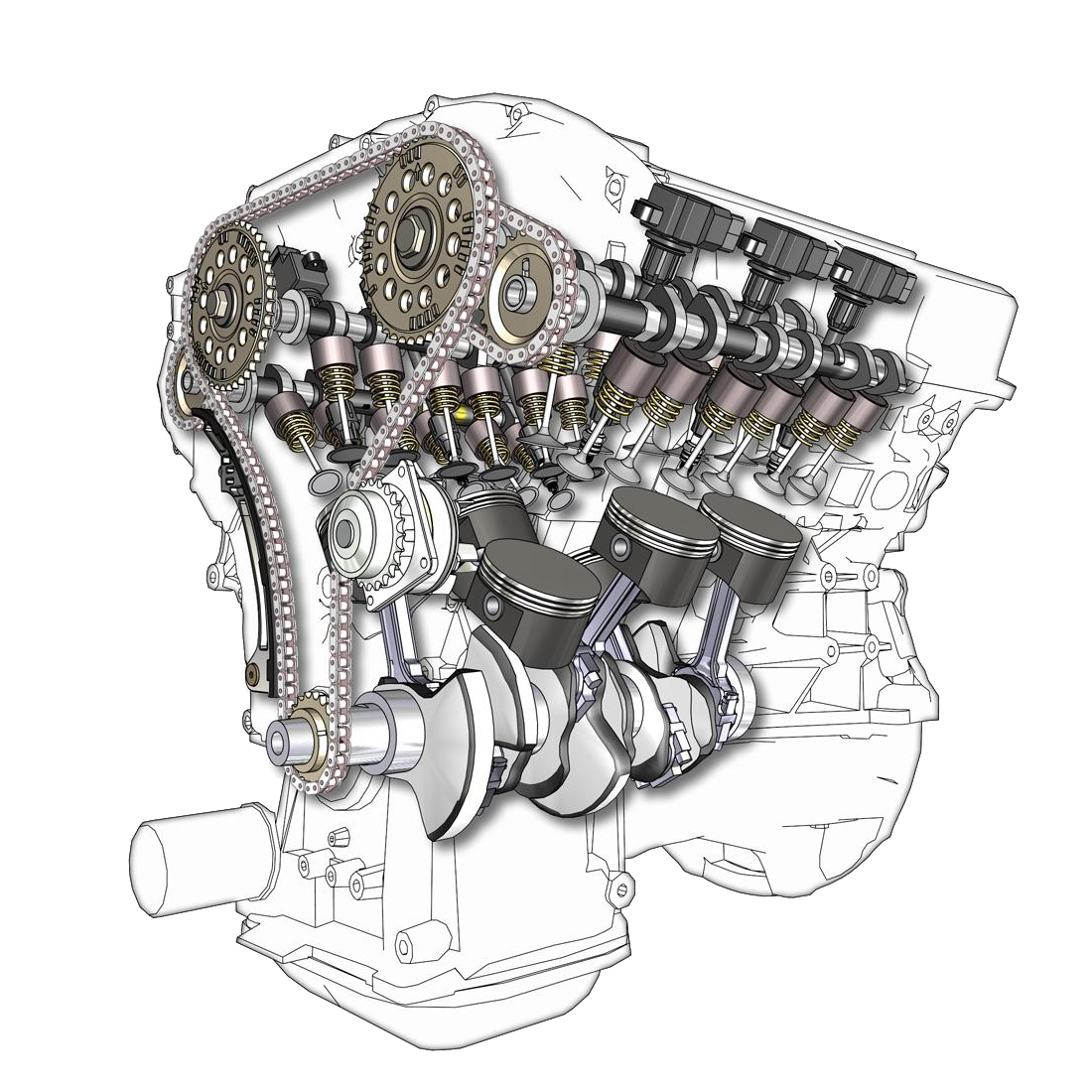

Reverse engineering science is said to come from answers to questions and in fact, the process of discovering the technological principles of a device, object or a system that is obtained through analysis of its structure an function. In most cases, the subject under discussion is a mechanical, electrical , software or a biological or chemical substance without having previous knowledge and only by separating and analyzing how it functions, is trying to create a new instance of it. Reverse engineering is mainly used in commercial and military use Reasons to Use Reverse Engineering Software renovation : As a whole reverse engineering is required to understand the current status of the program . Software maintenance: Reverse engineering of software can provide the necessary documentation to understand the current state of the system software. Product analysis : To see how works a product, what are its components, cost estimates, and identify potential property rights. Security review Obtain sensitive information to help assemble Diss and analysis of design of system components. Remove copy protection, bypass access restrictions. Make copies without permission - not confirmed. Scientific - training purposes For reverse engineering mechanical parts, required three main information that each of these information extraction requires methods, skills and specific experience and all of them are vital. Without a doubt, extract the required information for reverse engineering of industrial parts with possession of equipment, devices and proficiency in engineering software will not be possible. It requires a correct understanding of the role, functions and performance pieces, as well as work experience in similar fields. The main information needed to carry out reverse engineering projects are given below. . 1-Dimensions informations 2-ingredients ivformations 3-Manufacturing process This question may arise that a lot more information is needed to manufacture one piece. Information such as used environment, application, parts involved, the task of pieces in the collection, tensions actions and even longevity and cost of design, material and manufacturing process of a piece, are very critical, but as explained in the first article was reverse engineering, product design and production process, without over or even having knowledge of the design. In the coming weeks the expression of any of the information required to carry out reverse engineering process will be considered as a special case. http://solidworks-training-iran.persianblog.ir/post/52
Continue
Solidworks Product Data Management System Product Data Management – PDM , is a fifth-generation software for CAD ,is additional section of an application to search, control and manage data associated with a product. This information usually includes technical features, Builders and developer of product Information and consumed alloys and materials. Using PDM , especially in large industrial companies and collection allows people and different teams with different specializations at the same time work on the parts and sophisticated products with a wide range of features and standards. Two different versions of PDM software include: PDM work group and PDM Enterprise. Which version of the Work Group for companies with less than ten systems that use Solidworks as the original software. But PDM Enterprise version for companies with more than 10 systems have been proposed. another advantage of the Enterprise Edition is the ability to communicate between different software. this version even access and edit of reports and information files, such as files Office word / Exel offers for related parties. Another feature of this software to calculate the costs and time of production parts and products. Enterprise PDM, simulation units responsible for the internal communication in a company or project at different levels which helps you design to minimize mistakes and prevent from interfering with models, drawings and product information. http://solidworks-iran.blog.ir/post/Solidworks-PDM-enterprise-professional
Continue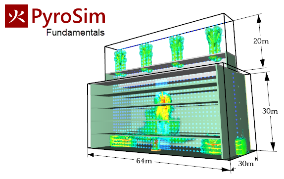
Pyrosim fire simulation Predicting how fires will spread, is one of the things that helps designers to prevent the spread of severe fires, using proper equipment. In this way, by creating a correct arrangement and choosing the right ventilation equipment, it is possible to help evacuate the smoke, and at the same time provide the conditions to prevent the expansion of the smoke layer and combustion gases downwards. Using pyrosim, you can see the hypothetical movement of smoke at the time of the fire. Fire simulation software such as FDS-Fire Dynamics Simulator software and Pyrosim software is one of the tools that can be used in this field. With the help of PyroSim fire simulation software, different scenarios during fires in places such as tunnels, parking lots, metro stations, residential complexes, gyms, cinemas, data centers, and factories can be studied. It should be noted that specialized firefighting software does not consider fire only as a source of heat, but in these applications, fire is a dynamic chemical reaction, which has different outputs such as heat and combustion gases. Is considered. To perform simulation and fire analysis, first, a three-dimensional model of the desired location should be prepared and then the simulation should be performed by specifying the material in the environment and the hypothetical fire location and intensity and type of fuel, as well as specifying the ventilation equipment. The outputs of fire simulation are: how the spread of fire and combustion gases, how the fire spreads over time, the temperature situation of different places during the fire, and the effective visibility of people in different places. http://tunnel-industrial-ventilation.blog.ir/post/PyroSim-FDS-Fire-CFD-Simulation
Continue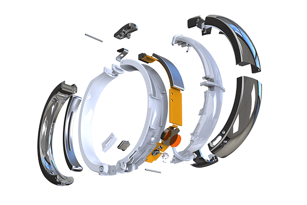
What does product design mean? Product design is the process of reviewing, providing solutions, building, and presenting a product to meet customer needs. Since there are no the same definitions of " product design " in different industries and disciplines, two general definitions of this concept are provided. One definition is a word and the other is a series of actions and activities. In a word, product design means the characteristics of an artifact including its form and shape (from an aesthetic point of view, the tactile sense of a device) and its function (including capabilities). But as a process, it means a set of actions and strategies, from the Idea Generation stage to the final stage of Commercialization. Basically, product designers conceptualize and evaluate different ideas and then define them as research in industrial and scientific formats. The role of product designers is to combine art, science, and technology to create services and products that people or companies use. The growing role of these people (product designers) is now evolving using the technologies and tools of the virtual world, which include software for design, analysis, simulation, and group building and integration. This software allows designers to communicate and analyze all aspects of the design by communicating effectively and like-minded, and finally provide products that, in addition to higher quality, require less cost, time, and manpower than in the past. Free download Solidworks training and tutorial PDF
Continue