In the SolidWorks part environment, what are the largest drawable model dimensions?
Solidworks software, like many design software, has predefined limitations. These restrictions are applied by the software manufacturer by default in different versions. In this article, we want to provide explanations about dimensional frameworks in SolidWorks.
One of the most important frameworks, is applied to the upper limit of sketch and feature dimensions in the Solidworks part environment.
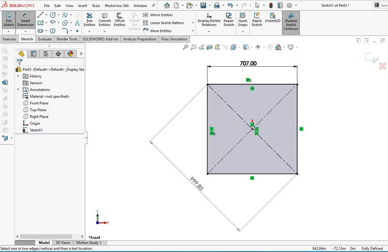
It might be interesting to know that, in a Part SolidWorks environment, you cannot sketch with one of its dimensions exceeds 1000 meters. If the length or width of one of the drawn lines or curves (side or diameter) exceeds a thousand meters, the software will warn you by giving a message that it is not possible to draw the desired sketch. In this case, an explanation is necessary. For example, if you draw a large square, the length of each side should not exceed 707 meters, because otherwise, the diameter of the square will reach over 1000 meters.

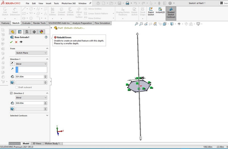
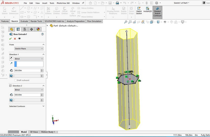
In addition to the sketch tab, the features section also has dimensions constraints. When you want to add volume to the 2D air drawing using feature commands (such as Extruded boss/base), you will have with a limit of 500 meters from each side. Of course, this 500 meter size frame in the section of SolidWorks profiles will apply to one direction. So you can add volume to the sketch by 500 meters in two opposite directions(1000 meters in total), as you can see in the following images.


Due to the dimensions limits, You can not create the part larger than 1000 meters(In any dimensions). But you can convert the desired model into smaller pieces. In such a way that the largest size is not more than a thousand meters. Next, you can enter these parts into the assembly part so that you can ignore part of the frames related to the dimensions.
Free download Solidworks PDF
Solidworks 3D model
Solidworks services